G3 Quick Start Guide
Quickly get up and running with a list of what comes in a development kit, setup instructions, and a demo to verify functionality. Once complete, visit the G3 Manual ![]() for more information on how to create applications for G3 modules.
for more information on how to create applications for G3 modules.
What You Will Find In Your Kit
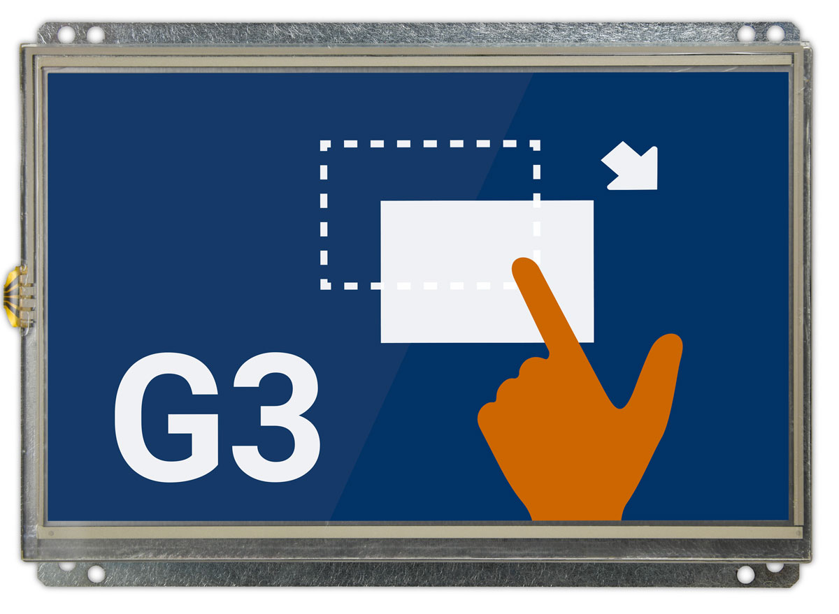
A 7″ G3BNG Resistive Development Kit is shown as an example.
Display Module
Power Supply, Cables, Flying Leads, and Accessories
In addition to the display module, you’ll find an accessory pack that comes with your kit. Cables and power supply will vary based on your controller board and display size. Additional accessories can be purchased online should you need them for prototyping or to replace items that have broken. Please contact Technical Support for any additional questions.
Setup Instructions
Learn how to set up the G3 module in a development environment. Begin by connecting cables and preparing for the initial power-on. Next, follow setup instructions for the Terminal Emulator on your Windows host, which includes identifying COM ports and configuring PuTTY and Tera Term for the Debug Interface and RS-232 port connections. Upon powering up, carefully observe boot messages and confirm the appearance of the demo UI on the LCD screen. Conclude the setup by exploring the medical demo for a more in-depth understanding.
* Note: Some kits have firmware installed on eMMC internal storage, and no SD card is needed.
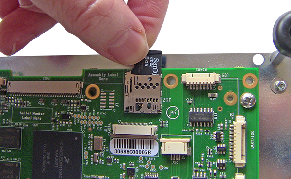
Insert the MicroSDHC Card
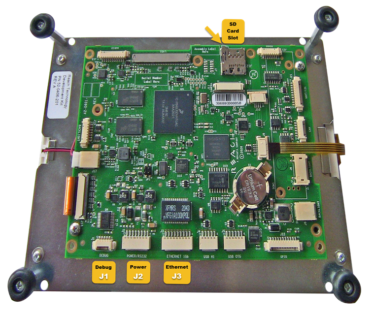
- Insert the included microSD card into the SD card slot (J12).
Connect the Cables to the G3 Module
- Turn the controller board face-up so that the debug port is facing you.
- Connect the debug interface cable to the debug port (J1).
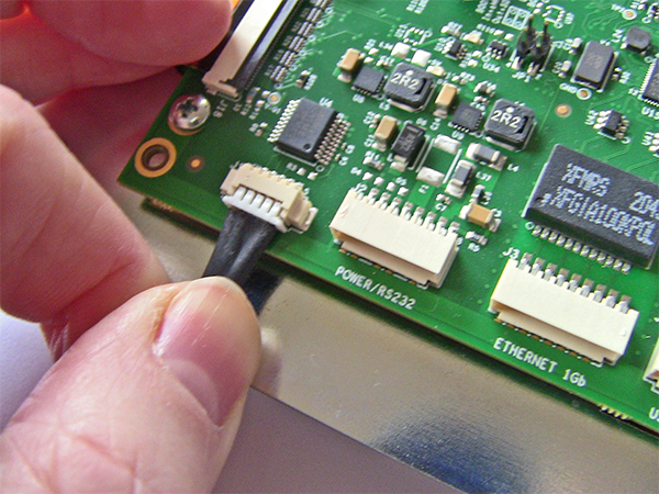
- Plug the AC mains cord into the AC adapter.
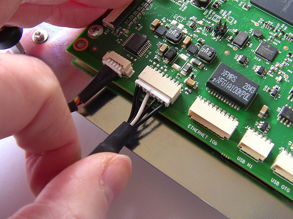
- Connect the Y-Type cable to the POWER/RS232 port (J2).
- Locate the USB to RS-232 adapter and USB cable.
- Insert the USB mini type-A connector on the cable into the mating socket on the adapter.
- Attach the male DB-9 connector on the USB to RS-232 adapter to the female DB-9 on the “Y” cable.
- Plug the USB type-A connector on the cable into your development host. Be sure to note the COM port on Windows or the /dev/ttyUSB device special file if on Linux.
- Connect the Ethernet Cable to the Ethernet 1Gb port (J3).
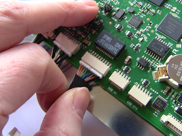
- Use the Ethernet inline coupler and a standard Cat 5e patch cable to connect your G3 module Ethernet cable to your network.
Important: Initial assembly is complete.
Do not power on the G3 module until you have completed the next section and have a working Terminal Emulator on your development host.
With physical connections complete, you can now add a Terminal Emulator application to your development host.
You will find instructions for a couple of alternatives. You only need to install one. We recommend PuTTY, which supports serial and network connections and runs on Windows 10, MacOS and Linux.
Important: The host instructions are for Windows. Do not power on the module for the following procedures.
Finding the Right COM Ports on a Windows Host
Note: Your Windows COM port numbers will vary depending on other serial devices plugged into your system, the USB port the cable is connected to, device driver revisions, and more.
- Open the Device Manager in Windows.
- Expand the ports (COM & LPT) section.
- The cable should be listed as a USB-to-serial COM port or something similar (with a COM port number in parentheses). In the image below, the COM port number is 5.
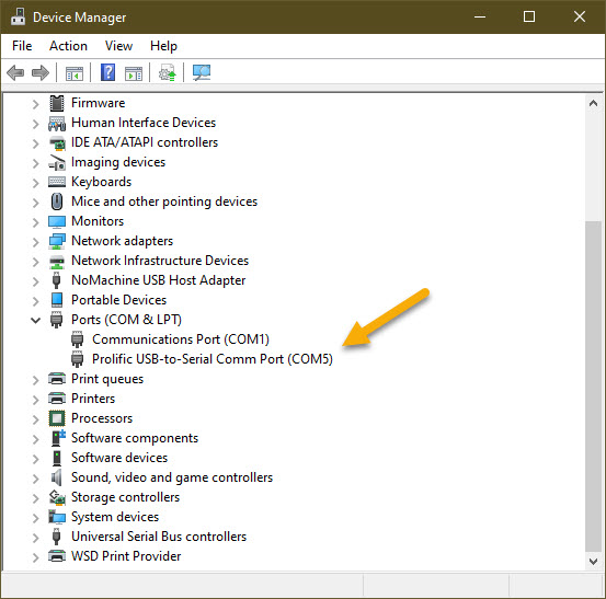
- Make a note of this port. You will need it to define a terminal connection to the G3 module.
- Repeat the steps above as necessary to identify the COM ports for the Debug Interface and the RS-232 port.
Note: Please substitute the COM ports listed on your machine for the following instructions, not the ones listed in our examples. Your values will almost certainly be different.
Install and Configure a Terminal Emulator
Next, install at least one Terminal Emulator application. You may want to set up and try them to decide your preference.
Tip: Configure two ports in your emulator: the Debug Interface and the RS-232 port.
Setup PuTTY
- Download and install the latest version of PuTTY.
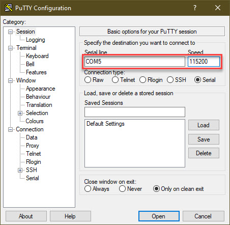
- Configure the serial port settings for the Debug Interface:
- Open PuTTY and select Serial for Connection Type.
- You can also use this dialog to create an SSH session definition once you know the IP address of the G3 module.
- Enter the settings as shown in the image below. Be sure to use the correct COM port determined for your setup in the steps above, not the one shown in this example.
- Open PuTTY and select Serial for Connection Type.
-
- To save your port configuration for future use, enter an easy-to-remember session name in the Saved Sessions box (e.g., G3 Console or G3 Debug), and select Save.
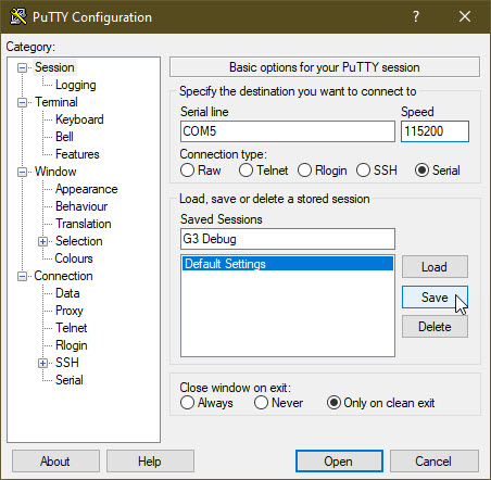
- Repeat for the RS-232 port.
Setup Tera Term
- Download and install the latest version of Tera Term.
- Configure the serial port settings for the Debug Interface:
- Open Tera Term, go to Setup -> Terminal.
- Enter the settings as shown in the image below. Be sure to use the correct COM port determined for your setup in the steps above, not the one shown in this example.
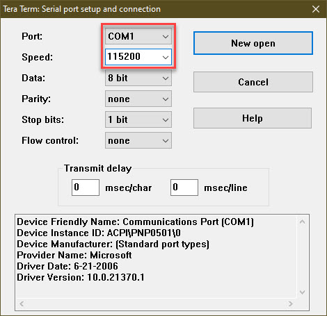
- Repeat for the RS-232 port.
Initial Module Power On
- You must complete the initial assembly and Terminal Emulator application installation described above.
- Ensure you have a Terminal Emulator open with the Debug Interface session open.
- Plug the AC mains cord into the wall.
- Connect the barrel connector plug on the AC adapter to the barrel connector socket on the Y-Type cable.
- You should see boot information and progress messages in the Terminal Emulator window.
- A few seconds into the boot, a splash screen, like in the figure below, should show on the LCD panel.
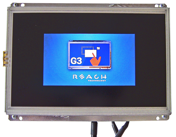
- A few seconds after the splash screen, you should see a login prompt in the Debug Interface Terminal Emulator session.
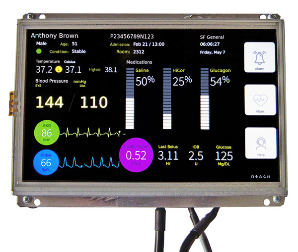
- Finally, the patient monitor UI medical demo should be on the LCD screen.
Tip: You will want a second Terminal Emulator session open on the RS-232 port for this section.
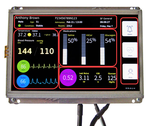
Several controls and informational sections are visible on the display, laid out for easy viewing and interaction. As shown above, the screen has several “hot spots” you can interact with and watch:
- The red boxes highlight several functional areas, including patient information, vital signs, medication controls, control data, and user buttons on the far right.
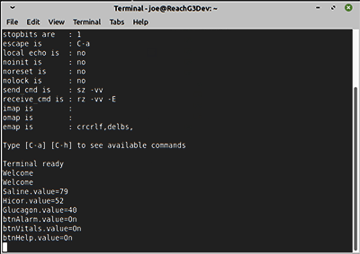
- In addition to showing Qt widgets on the screen, the demo provides an example of how applications can interact with your system hardware through the RS-232 port. The medication sliders are active and send resulting values to the RS-232 port upon release. The button states are also sent to the RS-232 port upon state change.
- The demo includes three operable sliders on the display: Saline, HiCor, and Glucagon.
- Move your finger up and down on each slider and observe the value changes on the slider itself. When you release the slider, the resulting value is sent to the RS-232 port. In this case, “Saline.value=79.”
The demo also includes three operable buttons along the rightmost edge of the screen:
- Alarm
- Vitals
- Help
Press each button. As the state of the button changes, so will the color. The medical demo uses the colors to indicate the button (and likely application) state:
- Activated
- Red (Alarm)
- Yellow (Vitals and Help)
- Deactivated
- Grey
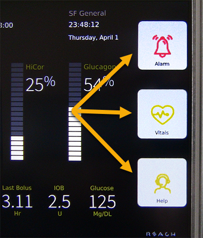
The buttons send data to the RS-232 port when pressed. In the Terminal Emulator screenshot above, we see several button state change messages, including “btnAlarm.value=On”, “btnVitals.value=On” and “btnHelp.value=On.” Try them out.
The text boxes react to command strings sent over the RS-232 port. The demo does not echo characters received on the RS-232 port, and the tty driver is not set to enable echo by default, so you won’t see the characters you type in the Terminal Emulator RS-232 port session unless you enable “local echo” in the Terminal Emulator port setup.
Sample Commands
This text file contains a list of commands to change values in the medical demo application.
Developer Virtual Machine (VM) Setup
For a streamlined development process, we provide pre-configured Developer VMs.
Reach Technology provides pre-configured Developer VMs for a few reasons:
- Different controller boards, with different processors, power G3 modules.
- UI development stacks are based on GUI toolkits.
- Installing a Yocto Software Development Kit (SDK) and integration with Qt Creator is complex.
Note: We recommend installing the Reach Technology G3 Developer SDK and GUI RAD tools on your Linux machine, provided you possess the technical proficiency for installation and configuration. The Developer VM is a viable option, offering a quicker installation process and final configuration. However, it’s essential to note that, like any VM, it may not deliver the same performance level as running the tools natively.
Follow the instructions below to install and configure the Developer VM on Windows, MacOS, or Linux.
TIP: When using a Windows host, ensure it meets or exceeds the requirements. See the requirements table below for minimum requirements. If your Windows machine is already running many tasks, you’ll need more CPU and/or more RAM. If you already have a lot of data on your disk, ensure you have at least 50 GB free.
| Item | Location |
|---|---|
| CPU | Four Core, Hyper-threaded i5 or Beter (Eight Hardware Threads) |
| RAM | 16 GB or Beter |
| DISK | 500 GB or Beter (Solid State Drives Preferred) |
| NIC | 100Mbit or Gbit Ethernet |
| VirtualBox Version | 6.1.16 or Newer (Matching Extension Pack) |
The G3 Developer VM runs in VirtualBox.
Installing VirtualBox
We recommend following these VirtualBox installation instructions.
Installing the G3 Developer VM
- Download the correct developer OVA from the G3 Software Download page.
- Open VirtualBox Manager.
- Launch the virtual appliance import dialog shown in the figure below:
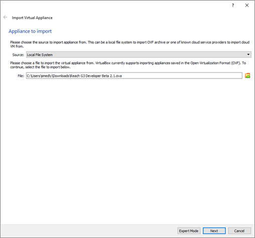
- The file textbox will be empty when the virtual appliance import dialog launches. Click the folder icon to the right of the file text box to launch the virtual appliance file selector and select the G3 Developer OVA file you downloaded previously.
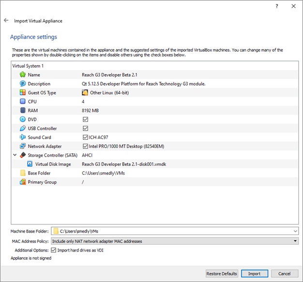
- Click Next to launch the virtual appliance settings dialog, which should look like the figure below:
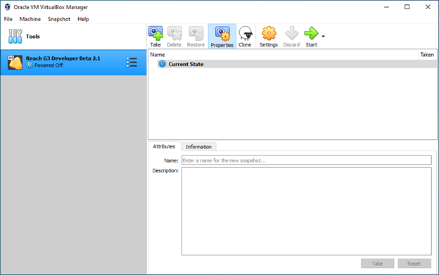
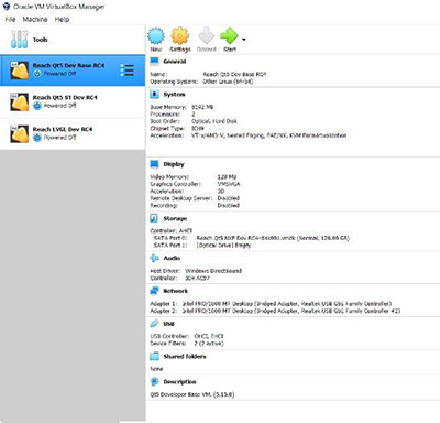
- Click Import to import the G3 Developer OVA. The VirtualBox Manager should now look something like this:
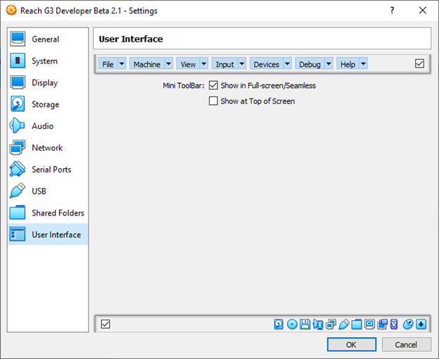
- Click the Settings button to verify that your appliance is imported correctly by ensuring the various settings match the figures below. There may be slight differences due to underlying host hardware differences (e.g., the number of CPU cores)—only update settings after you have read the Configuration section in the toggle below.
TIP: If you installed version 6.1.16 or greater, you’re done with the basic installation and can move on to configuration, if not, continue through the remaining steps to update the guest additions inside the virtual machine.
- Select the G3 Developer VM in the left column as in the figure below:

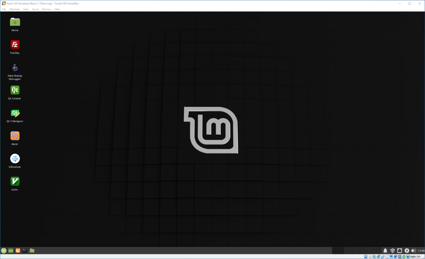
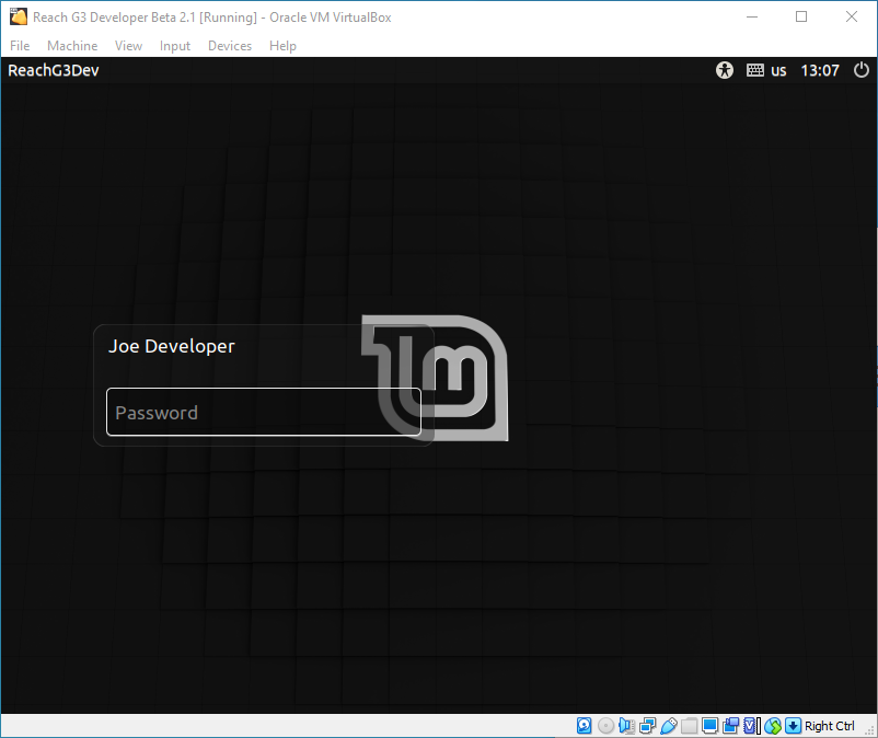
- Click the Start button to launch the virtual machine. You should see a window that looks like this:

- Login with the password developer. Your window should now look like this:
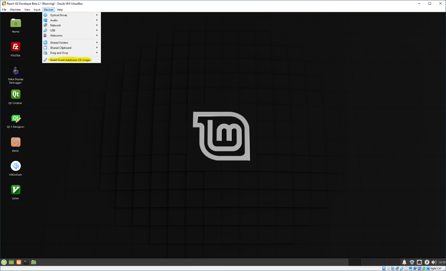
- Click Devices in the menu bar and select Insert Guest Additions CD Image. See the figure below:
After a few seconds, Linux Mint will automount the CD image and open a File Manager window.
- Click the terminal launcher button at the left end of the Linux Mint toolbar at the bottom of the desktop. It is the black one with the $ in it. Other than the command string in the terminal window, your Linux Mint desktop should look like this:
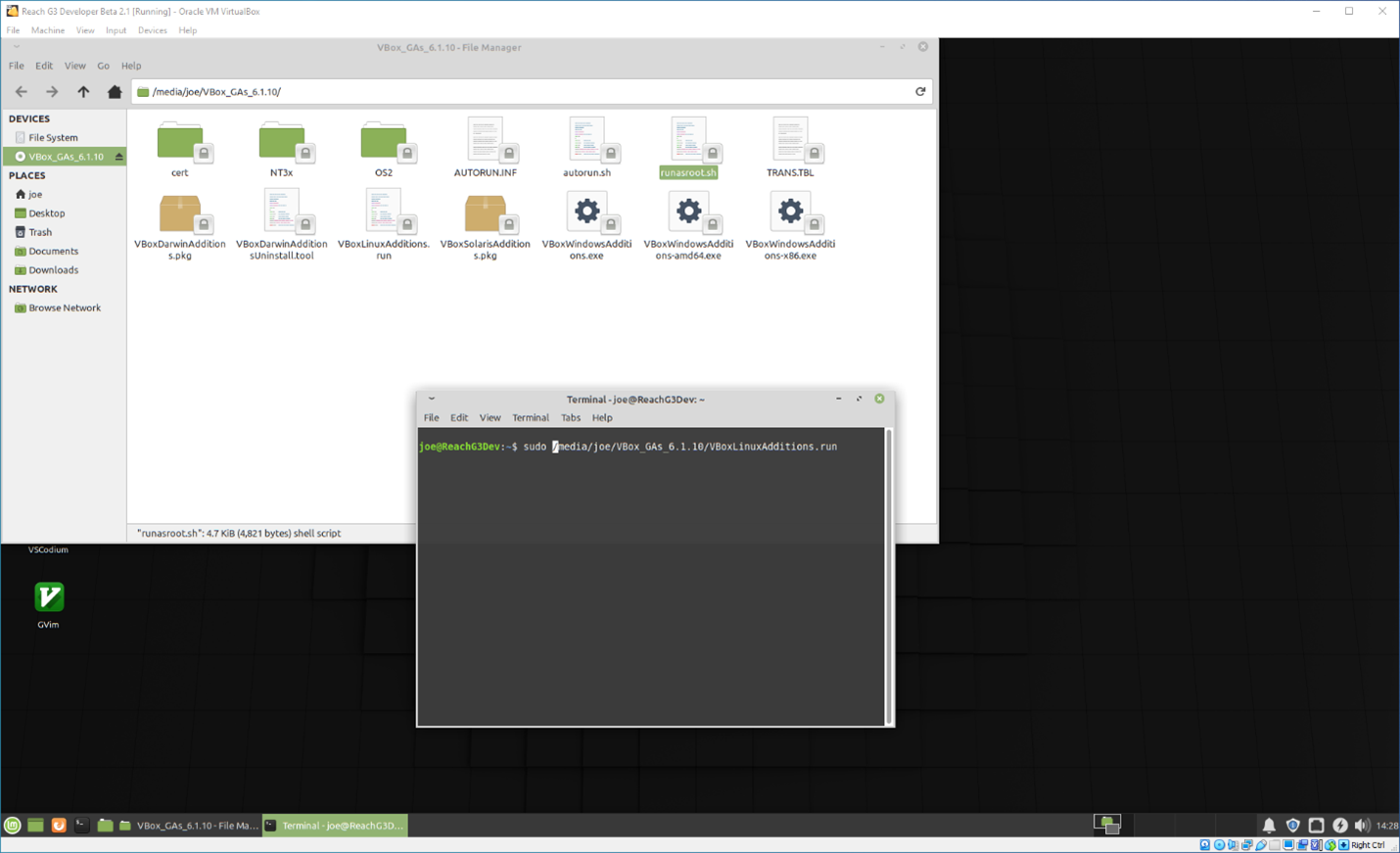
- Type in the command in the snippet below and press . This step will take several minutes. Wait until the green “joe@ReachG3Dev:~$” shell prompt returns.
![]()
Important: Remember to change the “6.1.10” number sequence to match your version of VirtualBox. Look at the path in the File Manager window to confirm the proper substitution value.
- Once the shell prompt is back, close both windows on the Linux Mint desktop by clicking the green X at the upper right corner of the window. Finish by shutting down your new Linux Mint 20 XFCE virtual machine.
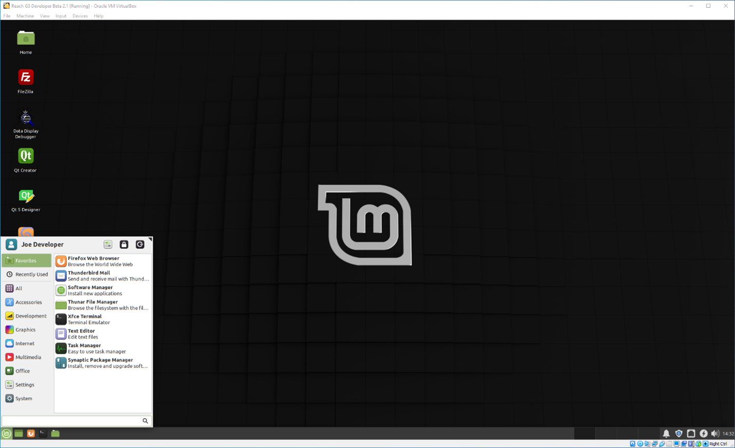
- Click the Linux Mint Start Panel button, the green one at the toolbar’s left. Your virtual machine window should now look like this:
- Click the power button at the very upper right of the Start Panel to popup the shutdown dialog, as shown below:
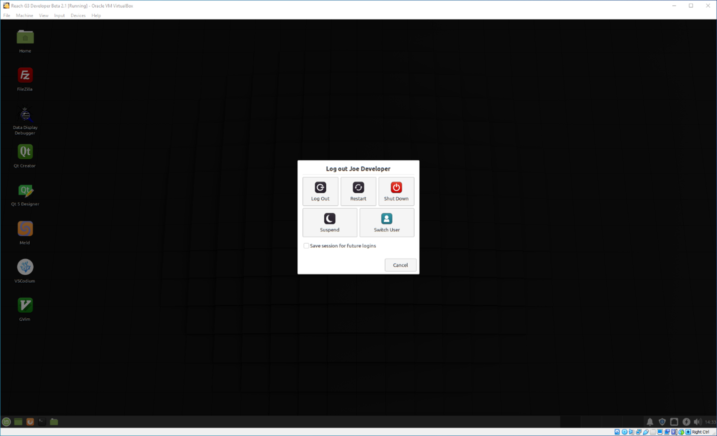
- Click the red Shutdown button to shut down the Linux Mint virtual machine.
- You can close that window if the VirtualBox Manager is still running.
The basic installation is now complete. Proceed to the post-installation configuration setup in the next toggle.
Important: Considerations when connecting a G3 module to a network.
Addressing security concerns when connecting any device to a network is crucial. Many IT departments forbid connecting devices not directly in their control. There are two options for dealing with this:
- Add a second network interface to the host PC (a USB dongle).
- Remove the PC from the main network and set up an isolated network (i.e., air-gapped from the main corporate network) for end-product application development.
No matter which option you choose, the development host and the G3 module must effectively have static IP addresses to allow communications for on-target debugging and migrating applications and associated data between the host and the G3 module without reconfiguring each time. You can do this by:
- Assigning the IP addresses manually.
- Configuring a DHCP server to use host reservations for the development host and the G3 module, which is equivalent to manually setting static IP addresses.
G3 Developer VM Settings for Windows
Adjusting some virtual machine settings allows you to use your development host hardware.
TIP: You can only adjust VM settings when the VM is stopped.
Before making any changes, complete these physical connections:
- Debug Interface Port.
- Ethernet Port (J3).
- “Y” power/RS-232 cable (J2), but do not power up the G3 module yet.
Settings You Must Change
You must change these configuration settings, or the G3 Developer VM cannot communicate with and control the G3 module target device.
Serial Port Configuration
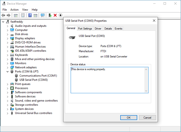
When you plug the USB connector from the Debug Interface Cable into your Windows 10/11 host, Windows will set up a new COM port for it. You may have to use the Device Manager to install the required driver the first time you do this. Search the network for the driver and pull the required one directly from Microsoft. When the driver is installed, your Device Manager should look something like this:
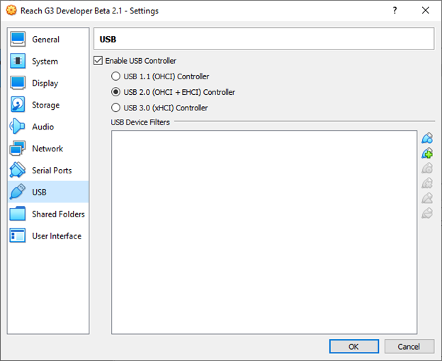
- Once this process is complete, open the VM settings dialog and switch to the USB panel. It should look something like this:
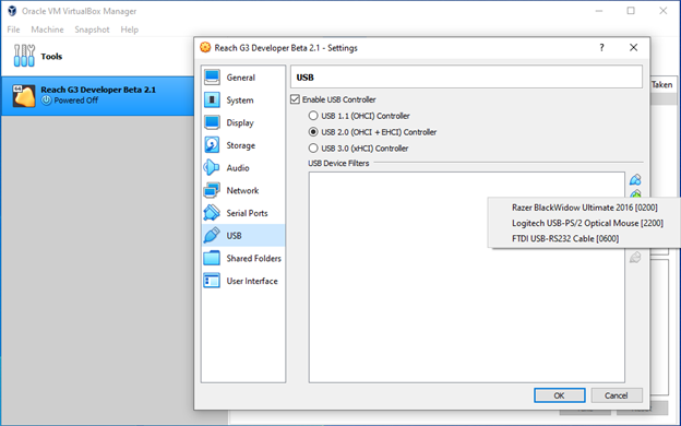
- Click the blue USB connector button with the green + on it to list the available USB devices as shown below:
- Click the FTDI USB-RS232 Cable [0600] entry to add the filter for the Debug Interface Cable. The VM USB settings panel should now look like this:
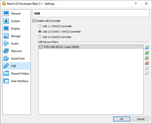
TIP: Remove all USB to serial converters and insert only the Debug Cable to make adding the filter easy. You cannot see the converter serial number until you add the filter.
- With the filter entry selected in the list, you can click the blue USB connector button with the orange gear on it to popup the device details dialog as shown below:
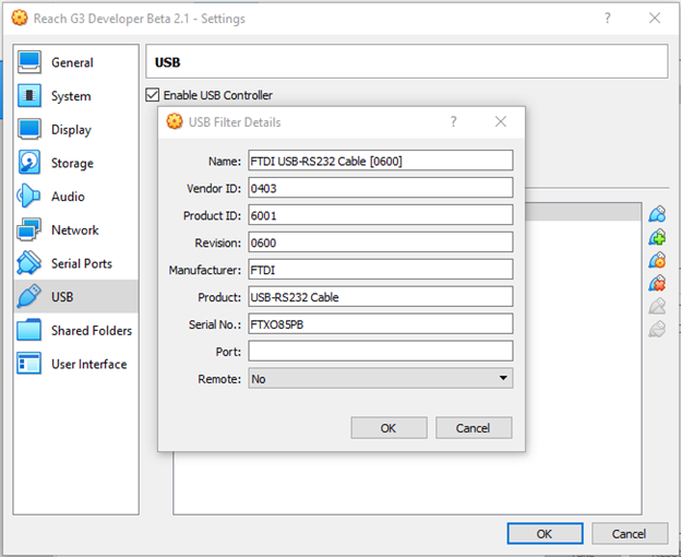
TIP: The main USB settings panel does not display the device serial numbers. They show up in the details dialog. So, if you have several similar USB devices (e.g., multiple USB to serial converters), the entries in the filter list will all look the same. Thus, you cannot tell which is which on quick inspection.
When first adding the filter, change the filter’s name on the details dialog for better identification in the main USB filter panel.
Testing
From the G3 Developer VM
Once you have configured the serial ports, launch the VM and log in as “Joe Developer.” The password is developer. Now, open a terminal window in the VM, then:
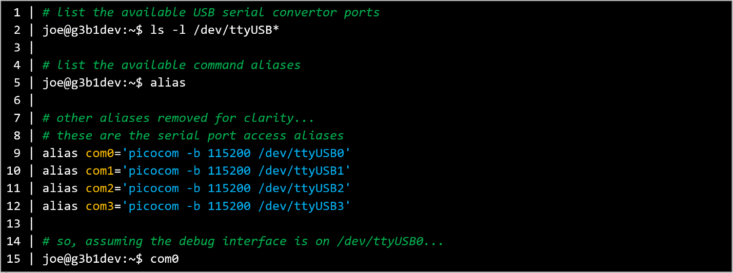
You can now see any messages and log in to the target in your terminal window.
Power on the target. You should see several lines of output as the target boots. Then, you will see a login prompt. Enter root; there is no password.
If you do not see any output, try any other available /dev/ttyUSB* ports listed by the above ls command. If there is no response, see Troubleshooting in the G3 Manual ![]() or seek assistance from a system administrator.
or seek assistance from a system administrator.
Ethernet Connection to the Target
This procedure applies to either the Linux desktop or within the G3 Developer VM. Start by opening a terminal window, then:
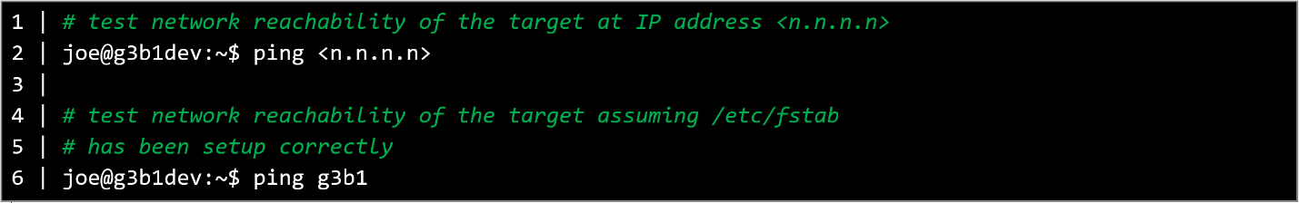
If there is no response, see Troubleshooting in the G3 Manual ![]() or seek assistance from a system administrator.
or seek assistance from a system administrator.
Now that you’ve installed the Developer VM, it is time to log in and explore.
- Open VirtualBox
- Select the VM in the sidebar and click Start (green arrow).
- Log in to the VM. The password is “developer.”
Important: The revision level of the SDK deployed in the VM must match the revision level of the G3 boot image.
In the Debug Interface Terminal Emulator session, type cat /etc/reach-release to see the image revision tag.
The image revision tag in the VM is built into the G3 Developer SDK path. Walk down the filesystem from /opt/reach/sdk until you find the directory name similar to the tag in /etc/reach-release on the G3.
They must be identical, or you will experience failures of your end product application on the G3.
Sample Applications and Demos
Find a comprehensive guide for creating and deploying Qt-based applications on G3 modules, demo examples and other sample applications. SAMPLE APPLICATIONS & DEMOS>
Next Steps
Start creating applications for G3 modules by downloading the G3 Manual ![]() . This comprehensive guide outlines the development process, covering both software and hardware aspects.
. This comprehensive guide outlines the development process, covering both software and hardware aspects.
Additional Resources
We are here to help. Do not hesitate to contact our technical support team.
Embedded Touchscreens Made Easy:
Up in Days, Smoothly to Production. Get started with a Development Kit.
Reach Technology is now a part of Novanta.
Sales and Engineering
545 First Street
Lake Oswego, OR 97034
503-675-6464
sales@reachtech.com
techsupport@reachtech.com
Manufacturing
4600 Campus Place
Mukilteo, WA 98275
service@reachtech.com
Please send payments to:
Novanta Corporation
PO Box 15905
Chicago, IL 60693
accounts.receivable
@novanta.com