G2Link
G2Link is a utility program that works with the G2 modules. It provides buttons for common tasks and a Serial Port Terminal Emulator for users familiar with UNIX terminals. It also has a network setup utility to configure an Ethernet or wireless connection to the display module.
Start with the power to the display set to OFF. Note: The network needs to be connected when the display module is powered-on so the display module can request a DHCP address and be accessible on the network.
Download and Install G2Link
Download G2Link (from the table below) and extract the files to a new folder, then run the file G2Link.exe.
| Version | Date | Change Log | File Size | Image |
|---|---|---|---|---|
| 1.0.9 | 02/16/2018 |
| 18.1 MB | G2Link-1.0.9.zip |
| 1.0.8 | 10/01/2015 |
| 6.2 MB | G2Link-1.0.8.zip |
| 1.0.7 | 09/23/2015 |
| 5.7 MB | G2Link-1.0.7.zip |
| 1.0.6 | 05/20/2015 |
| 4.5 MB | G2Link-1.0.6.zip |
| 1.0.5 | 1/12/2015 |
| 4.5 MB | G2Link-1.0.5.zip |
Connect the Display Module to Your PC
- Use Part Number: 23-0148-12 to connect the display module’s Ethernet cable to the same network the PC is connected to.
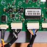 The 9 pin PICO connector connects to Ethernet 1 GB (J3) connector on the controller board. You may need to use the CAT5 coupler (provided).
 - Connect the Console cable (Part Number: 23-0161-72) to the PC. Connect the 5 pin PICO connector to DEBUG (J1). Make note of which COM port is assigned to the converter (see note below).
- Connect the miniUSB cable to the FTDI USB-Serial Port Converter, and connect the USB connector to the PC. Make a note in which COM port is assigned to the converter (see note below).
- If required, install the driver for the USB-Serial Port converter which is available on the manufacturer’s website (www.ftdichip.com/Drivers/VCP.htm).
- Plug in the round 5-Volt power cord to the display module.
Note: To check the COM port assignments in Windows, click on the Windows Start button, right-click on Computer, click on Properties, click on Device Manager, and click on Port. Look for “USB Serial Port (COMx)” where x is the assigned port number.
The main G2Link window has buttons for several common tasks.
Select Serial Port
Near the top of the window is the Select Serial Port button. When clicked, a dialog with a drop-down box will appear. Select which serial port to connect (use the COM port was assigned above by the operating system). Click Apply and Close.
In a moment, the program will connect to the display module and display a message stating the program is logged in to the selected port. If the program says it is waiting to connect to the port, make sure the display module is plugged in and started up.
Publish and Run
Opens a dialog box that offers to copy a selected folder with QML project files to the display module. Use the browse buttons to select paths to desired folders. The destination on the display module is app/src (or, /application/src if you are using the Advanced View or are logged into the display module’s debug port).
Restart QML Viewer
Restarts the viewer and runs the QML files (loaded via Publish and Run) on the display module. After restarting, any changes made to the QML files will be visible.
Reboot Module
Shuts down and restarts the display module.
Test Touch Screen
Closes the QML Viewer and starts the Touch Screen Test Program. A crosshair will appear in the middle of the display module screen to indicate where the screen is being touched. If the Draw button is pressed, a thin white line is left behind the crosshairs.
View Files in Explorer
Opens the Samba share location of the display module in Windows Explorer. From the file browser window, files can be viewed or edited directly on the display module.
Check Network Connection
Even though an IP address may display below this button, the display module may not be connected to the network. This can happen if, for example, an improper Static IP has been chosen in Network Setup. The text in this field can be copied, but cannot be edited. When the Check Network Connection button is clicked, a dialog will appear stating whether or not the display module is connected to the network. If it is not, use the Network Setup button below.
IP Address
This text box displays the current (or last-known) IP address of the display module. The text in this field can be copied, but cannot be edited.
Network Setup
This button launches a dialog to configure the display module’s Ethernet or wireless network connection. See the Networking page for more details.
The Advanced View is for users with basic familiarity with a UNIX command line. It is primarily a terminal emulator, but also includes additional tools to retrieve or edit information from the display module. To open the Advanced View, on the main window’s menu bar click on View → Advanced View. The Advanced View will open in a new window.
There are three important parts of this window:
- Text Output Area: Occupies the bulk of the Advanced View window. When a command is run, messages will be displayed in this area. Text can be copied from this area, but it cannot be changed or edited. When the window is resized the output area will resize automatically.
- Command Input Field: To send a command to the display module, type it in this field and either click the Send button or press the Enter key on your keyboard. This will send the command to the display module, and the command and the output will show up in the Text Output Area above.
- Command Buttons: See descriptions below.
Debug QML Viewer
This button stops the QML Viewer, the TIO Agent, and the SIO Agent, and restarts them in debug mode. This causes the programs to print extra information on the Text Output Area, which can be useful when trying to determine why messages from the external controller are not being seen by the QML application.
Edit SIO Settings
This button brings up a dialog to edit the Serial IO Agent settings, which edits the /etc/init.d/sio-agent file on the display module. The TTY port and baud rate of the SIO Agent can be changed.
View Module Information
This button activates a popup dialog box and displays information about the display module.
- IP Address: This shows the display module’s IP address used to communicate over the network.
- MAC Address: A unique number used to configure the display module.
Not in the popup, but in the Text Output Area behind it, the Kernel Version data shows how Reach Technology built the software installed on the display module. This information cannot be changed, but it can be selected and copied to other applications.
Save Startup Messages
Retrieves debug information about the display module. After a moment, a dialog will appear asking where to save the information, which by default is saved as dmesg.txt.
Publish to Flash
Publish to Flash is used to copy your QML application from the SD Card to the NAND FLASH. Start by uploading the application to the display module (when booted from the SD Card). Then, in G2Link, click on Publish to Flash. Progress will be displayed in the Text Output Area, but be sure to wait until you see the Finished message before restarting the display module. Here is an example:
publish-flash.sh
################################
Publishing Source
################################
UBI device number 0, total 1888 LEBs (239730688 bytes, 228.6 MiB), available 0 LEBs (0 bytes), LEB size 126976 bytes (124.0 KiB)
SRC found for QML
################################
Finished
################################
root@g2c-43-24:~#
Remember to move the jumper as described in the Using a Jumper to Select Boot Media section.
Restore Flash
Restore Flash is used to completely re-initialize the NAND FLASH from the SD Card. Start by writing the desired image to an SD Card, and boot the display module from that updated card. Then, in G2Link, click on Restore Flash. Progress will be displayed on the screen, but be sure to wait until you see the Done message before restarting the display module. Here is an example (edited for brevity):
upgrade-flash.sh
################################
Upgrading flash
################################

Erasing 128 Kibyte @ 0 --  0 % complete
Erasing 128 Kibyte @ 20000 --  0 % complete
Erasing 128 Kibyte @ 40000 --  1 % complete
…
Erasing 128 Kibyte @ 13e0000 -- 99 % complete
Erasing 128 Kibyte @ 13e0000 -- 100 % complete
ubiformat: mtd1 (nand), size 247463936 bytes (236.0 MiB), 1888 eraseblocks of 131072 bytes (128.0 KiB), min. I/O size 2048 bytes
libscan: scanning eraseblock 0 --  0 % complete
libscan: scanning eraseblock 1 --  0 % complete
…
libscan: scanning eraseblock 1886 -- 99 % complete
libscan: scanning eraseblock 1887 -- 100 % complete
ubiformat: 1888 eraseblocks have valid erase counter, mean value is 4
ubiformat: formatting eraseblock 0 --  0 % complete
ubiformat: formatting eraseblock 1 --  0 % complete
…
ubiformat: formatting eraseblock 1886 -- 99 % complete
ubiformat: formatting eraseblock 1887 -- 100 % complete
UBI device number 0, total 1888 LEBs (239730688 bytes, 228.6 MiB), available 1866 LEBs (236937216 bytes, 226.0 MiB), LEB size 126976 bytes (124.0 KiB)
Set volume size to 236937216
Volume ID 0, size 1866 LEBs (236937216 bytes, 226.0 MiB), LEB size 126976 bytes (124.0 KiB), dynamic, name "rootfs0", alignment 1
################################
Copying calibration file to NAND
################################
UBI device number 0, total 1888 LEBs (239730688 bytes, 228.6 MiB), available 0 LEBs (0 bytes), LEB size 126976 bytes (124.0 KiB)
################################
Done
################################
root@g2c-43-24:~#
Remember to move the jumper as described in the Using a Jumper to Select Boot Media section.
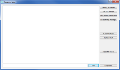 Stop QML Viewer
When clicked the QML Viewer will stop and will not restart. The touch screen test will also forcibly quit.
Send Ctrl-C
This button forcibly stops a long-running command. It sends the Ctrl-C signal to the terminal. It is useful for commands like ping which will continue running until killed.
If you have recently downloaded the latest version of our demo software, and you’d like to copy this into flash, this feature is available in the Advanced View.

Embedded Touchscreens Made Easy:
Up in Days, Smoothly to Production. Get started with a Development Kit.
Reach Technology is now a part of Novanta.
Sales and Engineering
545 First Street
Lake Oswego, OR 97034
503-675-6464
sales@reachtech.com
techsupport@reachtech.com
Manufacturing
4600 Campus Place
Mukilteo, WA 98275
service@reachtech.com
Please send payments to:
Novanta Corporation
PO Box 15905
Chicago, IL 60693
accounts.receivable
@novanta.com