Frequently Asked Questions
In our 30+ years helping customers develop products, we have collected and responded to many common questions. If you’re stuck, or not sure what to do next, give our Frequently Asked Questions (FAQ) a look. We may have already addressed your problem.
G2 Controllers
- All G2
- Application Consultants
- Communication
- Connectivity
- Development
- Environmental/Regulatory
- Features
- Fonts
- Getting Started
- LabView
- Mounting
- Performance
- Power
- Price/Availability
- Programming with Qt Creator
- Programming with Qt/QML/C/C++
- Screen
- Storage
- Troubleshooting
Learn about what I/O options you have and what they can do. To see which options are supported by each module, visit the Technical Specifications page.
| Type | Description |
|---|---|
| RS-232 | Standard way of communicating with locally attached external devices at up to 230 kbps. Standard is three wire: TxD, RxD, Gnd. |
| RS-485 | Industrial physical interface used for factory automation and long distance higher speed communications. Speeds up to 3 Mbps; half duplex standard, full duplex optional resistor termination. Powered by a rugged industrial driver. |
| Ethernet | Standard 10/100 Mbps Base-T full duplex; up to Gigabit on some controllers. Supports DHCP or static IP addressing along with the full range of IP settings and options. |
| USB | Can be used to connect to a PC or other host with a USB port. |
| WiFi via USB | Wireless connection via USB dongle. |
| GPIO | General purpose I/O, digital 0-3.3V signaling for output to individual indicators and input from discrete sensors such as switches or push buttons. |
| CAN Bus | Used in automotive communications buses, motor controls, and other industrial applications. |
| UART | 3.3V CMOS levels. |
| I2C | Used to connect to individual electronic sensor components, such as: temperature, humidity, accelerometer, etc. Can be used for general purpose GPIO expansion. |
| HDMI | HDMI Video output – display what you see on the LCD on a larger monitor/display. |
| Audio | Provides monaural microphone input and stereo audio output. |
| Real Time Clock | Battery backup clock. |
| Audio Beeper | Provides software controlled sounds. |
| Speaker | Audio output 1 Watt driver. |
If you are getting the error “file:///C:/Users/…/project.qml: File not found”, double-check the file path in settings.json to see if it is correct. It is created with the original pathname, so if you change any folder names in the path, then Qt will not be able to find the files.
To port a G2C1 application to the G2H2 platform, you will need to change the QML files to account for the new QtQuick used in the new Qt Creator. To do this:
- Double-click on the .qmlproject file to start the new Qt Creator.
- Click on Tools->Options…, click on Kits, click on Qt 5.3.1, then click on Make Default.
- In each .qml source file, change the line:
import QtQuick 1.1
to:
import QtQuick 2.0
- Click on File->Save All, then exit Qt Creator.
- Delete the .qmlproject.user file in your project folder – this removes any incorrect project settings (which are based on old file contents).
- Double-click on the .qmlproject file to start Qt Creator with the new settings.
Check out this Qt Developer Days video and download the Analyzing Performance of Qt Quick Applications document.
Yes, there is. We recommend getting a microSD extension.
We provide a Linux Virtual Machine (VM) and a cross compiler for use in coding C and C++ applications. Learn more by visiting the Linux Quick Start Guide.
You may need to purchase a license. Please contact support at The Qt Company for your specific answer. Learn more qt.io/licensing.
Due to the variety of platforms that QML runs on, by default, there are very few QML components available. Reach has provided a number of components to make development easier. Find them at QML Components.
The consulting company ICS has a series of videos that could be helpful. Registration is required.
The Qt Quick Controls module components are designed for desktop (mouse and keyboard) applications, not for touchscreens. As such, we do not support them. If there is a control in this set that does something our QML components do not, please let us know.
You must use the Edit mode in Qt Creator to change add/change items to a List Field. The Design mode is used for look and feel, while the Editor mode is used for entering GUI details.
 Qt Creator has a few quirks/bugs. Try switching to Edit mode and then back to Design mode.
If when you switch to Design mode you get the, “Using Qt Quick 1 code model instead of Qt Quick 2 (M324) error,” you are probably using the wrong default kit. You should be using the “Qt 5.3.1 Desktop” kit. Follow these steps to update your kit:
- From the Qt Creator menu select Tools -> Options.
- Click the “Build and Run” option in the “Options” pane, on the left-hand side.
- Under the “Kits” tab choose “Qt 5.3.1 Desktop” and click the “Make Default” button on the right-hand side.
- Click the “Apply” button at the bottom right-hand side.
The Help system built into our version of Qt Creator provides examples suitable for use in our environment. Examples found on the Internet may be for newer versions of Qt Creator which are not compatible with the version we supply.
We suggest you use the Qt Creator version provided. Newer versions change features and will not match the support materials we provide to you. Reach components are tied to a specific version. Newer versions may change the way Reach components are supported.
About Qt Creator
Qt Creator is the cross-platform IDE that makes UI development a breeze. Since time-to-market is key, the IDE includes productivity tools that speed up your development time.
G2H2 modules, with Qt 5.3.2, use Qt’s EGLFS platform, which takes advantage of the GPU and hardware acceleration. Qt manages the the frame buffer. We are not running a display server, X11 or Wayland.
G2C1 modules, which have no GPU, with Qt 4.8, use QWS to manage the frame buffer. Again, there is no display server such as X11 or Wayland.
How can I re-calibrate the touch screen?
You can force a re-calibration by removing the file /etc/pointercal and then rebooting the module. The calibration is then run during the module startup. It creates the file /etc/pointercal, and if this file exists at startup, the calibration step is not run.
You can also do a calibration manually by running these commands from the console (Advanced View in G2Link):
/etc/init.d/qml-viewer stop
ts_calibrate
/etc/init.d/qml-viewer start
Do I need to give the end-user of my equipment the option to re-calibrate the touch screen?
In the case of Projected Capacitance (glass front, PCAP) touch, the answer is generally no. Projected Capacitance touch works by energizing and sensing patterned rows and columns of lines in the touch panel. Calibration provides a correspondence between a location on the LCD and the touch’s sensed location. This won’t change over time, so one calibration should be sufficient. There could be a rare case such as where the calibration was done looking straight on, but the display is always viewed at an extreme angle; here the option for the user to re-calibrate might be helpful.
For resistive touch screens, the touch sensor surfaces don’t have discrete row and column lines, but still, the need for user re-calibration is not clear. Cars and other long-lived appliances use resistive touch screens and do not offer user-calibration. If there is a concern, then you can add the re-calibration option on a maintenance screen.
The Orientation page explains the changes required to rotate the display contents.
Note: This only applies to G2C1 modules, not G2H2 modules.
The Orientation page explains the changes required to change between landscape and portrait orientation.
Note: This only applies to G2C1 modules, not G2H2 modules.
You can test for the presence of “connection” with this approach:
The code above will use connection.sendMessage() when running on the display module but will use console.log() when running on the PC.
The QML Viewer section explains how to turn on “lookup acknowledgments” from the QML Viewer, which helps show which application messages are not working.
If your module is running from NAND, you edited system files, and your module doesn’t boot properly from NAND anymore, you will have to restore the base image. This will delete any work you have done (sorry!). Insert the SD card with the image you want (find the appropriate Software Releases by going to the “Touchscreen Display Module” menu, selecting your module and looking in the “Downloads” tab) and remove the NAND boot jumper. Then use the View, Advanced View option of the G2Link program and click the Upgrade Flash button. When the update is finished, reinstall the jumper and power cycle. Then re-install your application to NAND.
To re-calibrate the touchscreen, log into the console and use the command:
ts_calibrate
After that, you can use the command
ts_test
to check the touch operation.
This is not our core competency. We suggest that you look at products from Beijer Electronics which are designed for rugged applications.
You can get the VM’s time synced with the host system by starting the VM, then in the upper-left corner, click Player->Manage->Virtual Machine Settings… Then click the Options tab, VMware Tools, and check the “Synchronize guest time with host” checkbox. Then click OK.
You can do the same thing from the VMware Player start-up screen by clicking on the desired VM, then click, “Edit virtual machine settings,” then click the Options tab…
After you either reset the VM or power it off then back on, the time should be the same as on the host system.
Our display modules do not support a package manager (e.g. opkg) to install new packages. Package managers require extensive support from the vendor to provide pre-compiled packages for the target platform, and a server infrastructure to make the packages available to customers.
Currently, Macs are not supported since some QtCreator IDE plugins need to be compiled for the development machine OS.
G2 modules run a custom Linux distribution (build) Reach Technology created. Since standard distributions come packaged with many components and packages not required on our display modules, it is not based on any standard Linux distribution.
All the development kit hardware and software to prototype a touchscreen display is the same, however, the Qt Development Software is geared toward either Windows or Linux users.
Note to Windows Developers:
While our touchscreens are Linux-based – that doesn’t mean you need to be a Linux developer to use them.
Our solution allows developers to use Windows GUI tools to develop their application and then load it into our display controller to run. Write a complete graphical interface, test it out on the PC, and then drag the application over to our display module’s file system to run. It runs the same as on the desktop. Reach has developed a suite of drag-and-drop interface components for quick prototyping.
Whether you develop in Qt or QML, you can run the same code on the PC or the target. Reach does all the work of configuring Linux and making it run your GUI code. Reach provides customers with custom start-up screens and specialized I/O agents (processes) to connect the GUI to the outside world.
You may need to purchase a license. Please contact support at The Qt Company for your specific answer. Learn more qt.io/licensing.
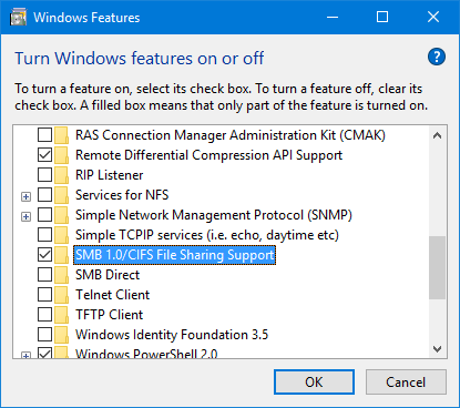
Microsoft recently changed their security policy to use Samba 2.0 instead of Samba 1.0, and have disabled Samba 1.0 by default. Our module uses Samba 1.0. Use the steps below to enable Samba 1.0, and this should fix the issue.
- On Windows 10, starting with build 1709, Microsoft has deprecated and disabled SMBv1 in favor of v2 for security reasons.
- This will cause G2Link to get an error when trying to Publish and Run a QML application, saying that the path does not exist.
- If you see this error, you can check which build of Windows 10 is on your system with the “winver” command. It will give you a screen such as:
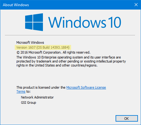
Note: The above screenshot is showing Version 1607 instead.
- If your system is showing version 1709, you can use the steps below to work around the problem.
-
- Start Control Panel, click on Programs, then in Programs and Features, click on “Turn Windows features on or off”. In the window that pops up, scroll down to the item “SMB 1.0/CIFS File Sharing Support”:
-
- Check the associated check box, then click on OK. You may need to restart your system for the change to take effect.
- G2Link should now be able to access your display module.
-
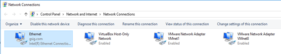
This issue rarely occurs, and it is due to an unknown configuration setting in the Windows system. We have not been able to determine why this occurs, but we have a workaround, which is to add a Windows credential for the display module. Use these steps to add a credential:
- Open Control Panel.
- Click on “User Accounts”.
- Click on “Manage Windows Credentials”.
- Click on “Add a Windows Credential”.
- In the new window, enter the display module’s IP address, enter ‘root’ for “User name:” and leave “Password:” blank.
- Then click on OK.
It is luck-of-the-draw on whether the driver in our kernel supports any given USB-Ethernet adapter or not. The adapters use one of many different controllers, and some might work while others do not. Even if you find one that works, you might not be able to get the exact module again because the vendor will change the internal controller. Because of this driver/controller issue, we don’t support the USB-Ethernet feature.
Reserved I2C devices addresses vary based on the module. Find G2C1 and G2H2 addresses in the tables below.
G2C1 Reserved I2C Device Addresses
| Address | Device | Description |
|---|---|---|
| 0x38 | PCAP Controller | PCAP controller on touch screen flex cable (if installed). |
| 0x3E | GPIO Port Expander | GPIO port expander attached to GPIO port on connector J8. |
| 0x55 | PCAP Controller | PCAP controller on touch screen flex cable (if installed) (alt.). |
| 0x68 | RTC | Real-time clock module. |
G2H2 Reserved I2C Device Addresses
| Bus | Address | Device | Description |
|---|---|---|---|
| 0 | 0x0A | CODEC | |
| 0 | 0x1D | Temp Sensor | |
| 0 | 0x38 | PCAP Controller | PCAP controller on touch screen flex cable (if installed). |
| 0 | 0x3E | GPIO Port Expander | GPIO port expander attached to GPIO port on connector J8. |
| 0 | 0x68 | RTC | Real-time clock module. |
NOTE: Bus 0 is an internal I2C bus. Bus 1 is available on connector J21 (full-stuff modules only).
Yes, our controllers with the CAN option support the CAN 2.0B protocol specification.
This is covered in our Application Note, AN-117, found in the Application Notes section in the G2H Software Documentation.
The On-Board Flash section discusses the process.
The SD Card section discusses the tools you can use.
To move QML code to the display module, follow the instructions below based on your user type.
Windows Users
Reach Technology has developed a Qt application called G2Link. It has a “Publish and Run” button that copies files to the display module, then restarts the QML Viewer. Visit G2Link to download the software and learn how to use this simple tool.
Linux Users
See Linux Deploy.
Network Connection
For information about connecting the module to your network, see Networking.
The +5_EXT signal is for powering small external circuits. This signal comes from the +5V DC input to the display module and is routed through a PTC resettable fuse. The PTC has a rating of 2A at 20C or 1.5A at 60C, and this is the power budget for the combined total of all +5V_EXT outputs. Also, each individual +5_EXT pin is limited to 1A max.
The baud rate is set in the init script on the module: /etc/init.d/sio-agent.
You can change this using various approaches. If you’re familiar with Linux and the ‘vi’ editor, you can use a terminal emulator connected to the debug port, login as ‘root’, with no password, then edit the file, and change the default baud rate to another. Simply reboot the module for the change to take effect.
Another approach would be to use G2Link. Connect to the display module’s debug port with the “Select Serial Port” button, then click on View>-Advanced View, then click on “Edit SIO settings”. You can select the desired baud rate from the pull-down, then click OK. This will edit the sio-agent script for you.
Another approach is to use G2Link, connect to the debug port as before, but then click “View Files in Explorer”. When the file browser window appears, click on “conifg”, then click on “init.d”. You can then use a standard editor to edit the file. NOTE: do not use Windows’ “Notepad” application – it will mangle the file.
UART is one of the onboard interface options available on display modules. Linux device names can be found in the tables below by model type: G2C1 and G2H2. Read more about I/O Options between modules.
G2C1 UART Names
| Location | uP Port Name | Linux Device Name | Description |
|---|---|---|---|
| J3 | AUART1 | /dev/ttySP1 | Input main 5V power and RS232 |
| J5 | DUART | /dev/AM0 | Debug console port |
| J7 | AUART4 | /dev/ttySP4 | RS485 port 2 |
| J9 | AUART2 | /dev/ttySP2 | I2C/3.3v UART |
| J11 | AUART0 | /dev/ttySP0 | RS485 port 1 |
G2H2 UART Names
| Location | uP Port Name | Linux Device Name | Description |
|---|---|---|---|
| J1 | UART1 | /dev/ttymxc0 | Debug console port |
| J2 | UART2 | /dev/ttymxc1 | Input main 5V power and RS232 |
| J21 | UART5 | /dev/ttymxc4 | I2C/3.3v UART |
| J25 (if installed) | UART4 | /dev/ttymxc3 | RS485 port |
A universal asynchronous receiver/transmitter, abbreviated UART, is a computer hardware device that translates data between parallel and serial forms.
In order for your microcontroller to communicate with the QML Viewer (a tool for loading QML documents that makes it easy to quickly develop and debug QML applications) messages being sent need to be translated. We have created a set of tools called the Serial Input/Output Agent (SIO) and Translator Input/Output Agent (TIO) to make this microcontroller interface translation happen.
You might also benefit from watching this 11 min video on the architecture.
The architecture assumes the display modules run the high-level Graphic User Interface (GUI) and interfaces (over serial, Ethernet, CAN, etc) to other intelligent agents that perform the embedded product’s Core Functions (such as running a skin laser, process control, sorting vegetables by color). Reach provides the software components needed to connect the GUI to an external microcontroller via a serial port. This includes a translation layer that insulates the Core Function microcontroller from GUI changes. This separation allows GUI design to be flexible, as useful and intuitive interfaces have to be designed interactively among marketing, design, and user stakeholders without requiring the embedded microcontroller code to be changed.
Microcontroller Interface Architecture Video Transcript
What I want to do is just give you an overview of the microcontroller interface architecture of the G2 system and explain why we have done certain design choices. What we have, is we have the actual graphic engine and it’s QML, QT based. This is the thing that actually draws the stuff on the screen. This is the underlying implementation. What you’d see on the screen obviously, would be a combination of knobs and buttons and dials, or whatever, and numbers. This is what you see on the screen. The question is, “Great, I have this graphic thing. I can move the knobs and push buttons, but how does that relate to the underlying core functionality? When I push the button, how does it turn a light on and off, or whatever?”
In the QML world, what we have done is rewritten the viewer component. It’s called a viewer. This actually drives this. What the viewer does, is set up the environment for this microcontroller interface but then it supplies … it provides a connection out the end and this is an internal connection in the computer, so this is what we call the QML Viewer. It runs the files that you create, which are in QML in JavaScript. Then it talks to what we call an agent, a TIO agent. It’s a pipe, it’s an internal pipe in the computer, in Linux. What the TIO agent does, we think is very important. Well, let me just do the whole thing. I’ll do the whole thing. You have the TIO agent and then it talks to an SIO agent, and this actually talks to the physical serial port, and that would go to the embedded microcontroller that is doing your underlying core functionality. This may look complicated but I will explain why we are doing it this way.
First of all, the serial agent … the reason for this architecture is again, divide and conquer. What the serial agent does, is connect the physical layer to the logical input of the computer, and this sets the baud rate and other characteristics of the physical line. Now you could replace this with a different protocol. For example, if you wanted RS-485, if you wanted modbus, profibus, CAN bus, whatever, because on here this is the logical … this is the message interface. And how the message goes to the final guy, you don’t really care from this side. So we have a message interface. This is the SIO agent. Customers can change this as the protocol. This is an interchangeable part. You can put whatever you want for the particular protocol.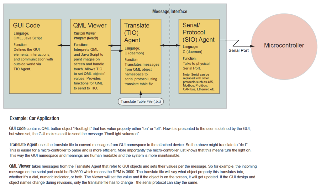
For example, if this was going into a car, this would be a CAN bus interface and the messages on this side of the barrier would be things like speed, RPM, whatever. They are the messages coming back that is interacting with the guts of the car. Then we have this translate agent and the translating agent is in my mind very important. Because what happens is that at this level, on this barrier, what comes on this side are messages but they are still very much low level related to whatever the microcontroller is doing. For example, and I will give you a car example. What is coming across here might be simply a byte, or it says RPM, R for RPM, and then maybe four digits, 1200. It’s really low-level. It’s very much specific to this and trying to get the GUI to understand what this is, it doesn’t relate to the namespace in the GUI.
The people doing the GUI are all in terms of object-oriented namespaces of controls and indicators, whatever. Also, if you tied the GUI directly to this, they become tightly coupled and it’s much harder to change this. What we do is we have a translate agent and what the translating agent does is take this low-level, not just domain-specific but interface-specific information, and translate it. We have a translation file. The TIO agent takes in a translate file, translate.text and this simply says when you get a message R followed by a digit … let me do this. For example, you would say R%D followed by a digit translates into, for example, RPM.value = the number, say %D. Long story short, it changes this into something that makes more sense for the GUI designer.
What is great about this, this translate concept is it means that the definition, this API – the API for the underlying microcontroller and these guys don’t have to be in lockstep. They don’t have to be one-to-one. If this guy decides, “Oh, I want to add an extra digit here, or I want to change the physical format of the messages, of the types of messages I get,” by just changing the translate table, you can use the same GUI. We want it to be able to do … again like I said, divide and conquer. I want to be able to change this if it’s going from a push button to a slider, to any different kind of I/O control – I don’t have to change this guy’s code. I can simply change the translate table that says instead of button maps to this functionality, I can say slider maps to this functionality, or whatever I want.
Again, the idea is that the implementation of the GUI, you can change this as desired for the users without having to force the embedded microcontroller implementation to change. Because you do this, you test it, you should leave it alone. You don’t want to keep … We have a rule. You open the computer, lose a day, install software, lose a day. Whenever you touch something, there is a good chance you’re going to break it. Keeping things as stable as possible is a big deal, and the translating agent helps to do that by providing this translation layer. It helps to keep this stable … independent of GUI changes.
The internals of our G2 system, because it has the viewer, the translating agent and the serial agent. It might look a little complicated but it’s fairly easy to understand. It is more maintainable and it does the divide and conquer. We think it’s the right way to go, and the people we have talked to like it too. Again, what is nice about this is if instead of for example a serial port, you wanted to use … go over Ethernet, so this would be Ethernet TCPIP. All the details of that are hidden from the TIO agent. It’s just passing messages back and forth. It doesn’t care what the physical characteristics are. All of the G2 products are running embedded Linux, but to be honest you shouldn’t have to worry about that. Our job is to hide that from you. What we do is we ask you simply to write files in QML, which is this essentially Qt markup language. These are interpreted and you also write in a file JavaScript. This can completely define the graphic user interface.
Then what we have is on the embedded device – on our display module, on our graphic engine – we have something called a QML Viewer. What it does is it takes these files and interprets them to come up with whatever the display is. If you have a meter at 12.34, some buttons, selectors, dials, knobs, whatever you want. These are all defined by the QML and the JavaScript. The QML viewer is the one that paints it on here and interacts with the outside world through the translating agent (TIO) and the SIO agent. The idea is, the actual implementation of it is, it’s quite nice. You are sitting at your PC. On the screen, you are designing your graphic interface, knobs, switches, whatever. What you are actually doing is you are designing it and the output will be QML files and JavsScript. Then once you are happy with the look and the feel of it, you can simply take these files, and drag them over so that on your PC you have a file folder window with files.
This is the display, the G2 display engine. You simply take these files. This display engine has a Samba server. It has a file server just like you have in Windows. Within the development environment here at Linux or Windows, you can have a file explorer, which is a window into the files on this display engine. When you’ve finished designing this, you take these files, you drag them from… let me see if they were in a file explorer here. You locate them. You take these, you drag them into here. It automatically puts it on the engine. You restart the engine and then you have the thing you just designed. It’s running on the engine. That is the methodology of development.
Here’s how to connect a G2C1/G2H2 module directly to a PC:
- Plug the debug cable into J1 on the module board and into a USB port on the PC.
- Plug the Ethernet cable into J3 on the module board and into the Ethernet port on the PC. Use a coupler if needed.
Windows 7/10 Setup
- Control Panel > Network and Internet > Network and Sharing Center > Change Adapter Settings
- Right-click on “Local Area Connection” or “Ethernet” and choose Properties.
- Double-click on Internet Protocol Version 4 (TCP/IPv4).
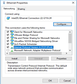
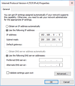
- Click “Use the following IP address” and enter the following:
- IP Address: 192.168.0.5
- Subnet mask: 255.255.255.0
- Default gateway: Leave blank
- Click “Use the following DNS server addresses” and leave both fields blank.
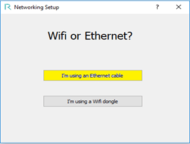
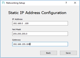
G2Link Setup
- Network Setup > I’m using an Ethernet cable > I’m using a static address.
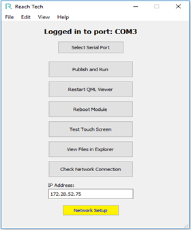
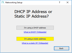
- IP Address: 192.168.0.100
- Subnet Mask: 255.255.255.0
- Default Gateway: 192.168.155.100
Embedded Touchscreens Made Easy:
Up in Days, Smoothly to Production. Get started with a Development Kit.
Reach Technology is now a part of Novanta.
Sales and Engineering
545 First Street
Lake Oswego, OR 97034
503-675-6464
sales@reachtech.com
techsupport@reachtech.com
Manufacturing
4600 Campus Place
Mukilteo, WA 98275
service@reachtech.com
Please send payments to:
Novanta Corporation
PO Box 15905
Chicago, IL 60693
accounts.receivable
@novanta.com